Visual Studio 2015 Uml Class Diagram From Code
Code Generation from UML Class Diagram in Visual Studio 2012 Ultimate
Posted by: Mahesh Sabnis , on 9/6/2012, in Category Visual Studio
Abstract: The UML Diagramming and code generation tool in Visual Studio helps a Solution Architect setup boilerplate code for the rest of the team thus reducing possible friction in design-intent and implementation. In this article, we will explore this tool.
Visual Studio Ultimate editions have application design support using the "Architecture" menu in the Menu bar. In an Enterprise setup, it is often the case that a solution designer expresses intent of the solution using UML Class diagrams, Sequence Diagrams, Use Case diagrams and passes these to the developer. Now if a developer does not understand these diagrams, then there are chances of mistakes during coding. Visual Studio 2010 Ultimate and Visual Studio 2012, come with Architecture diagramming tools that help build these UML diagrams e.g. UML Class diagrams. These diagrams can then be used to generate the code directly.
There are some changes between VS 2010 Ultimate and VS 2012 Ultimate for code generation from UML class diagrams. In VS 2010 Ultimate, Visual Studio 2010 Feature Pack 2, must be installed to generate code from UML class diagram. Note that MSDN subscription is required to download this Feature Pack 2.
Except the Code Generation from UML Class diagram, all other features in the article are similar in VS2010 Ultimate and VS2012 Ultimate.
If you open Visual Studio 2010/2012 and select 'Architecture' menu > 'New Diagram', you will get the following Window for selection of various diagrams:

- Class Diagram:
- These are used to describe various objects used in the application system.
- With the help of class diagrams, it is easy to find out objects and its relationship between each other.
- Sequence Diagram:
- These are used to represent interaction between different objects used in the system.
- These diagrams are basically used to provide information about the messages between different objects.
- Use Case Diagram:
- This is the representation of the interaction between end-user and the application system.
- Activity Diagram:
- This diagram represents the flow of the application system in Workflow manner.
- It is also known as the detail representation of the Use Case Diagram.
- Component Diagram:
- This is high level representation of the entire application system.
- It represent various component used in the system e.g. UI component, External Web Server system, databases etc.
- Layer Diagram:
- This is one of the most important diagram in software design.
- This diagram is used to represent logical architecture of the system e.g. Data Access Layer, Business Logic Layer, UI layer etc.
- This diagram helps in validation of the application after coding where the dependency between the layers of the application system can be validated.
Class Diagram
As mentioned above, class diagrams provide information about objects used in the system and the relationship between them. The purpose is to focus more on the logical aspect of the classes without bothering about their implementation. Relationship between objects like inheritance, association etc. can be easily represented by a class diagram. Thus a Solution Architect can use the same IDE as the developer i.e. Visual Studio, to render a representation of the problem.
Step 1: Open Visual Studio and create a blank solution, name it as 'VS2012_Models_Diagrams'. In this solution, right click and add a new Modeling project, name it as 'MDL_CodeGenerator_Class_Diagram' as shown below:

Step 2: Right click on this model project > Add New item > UML Class Diagram, name it as 'HMSClasses' as shown here:

You will see a Class Diagram designer. Observe the toolbox:

The toolbox is really self-explanatory, we have been provided with icons for creation of Class, Interface, Enum, Inheritance etc. which is frequently required for application design.
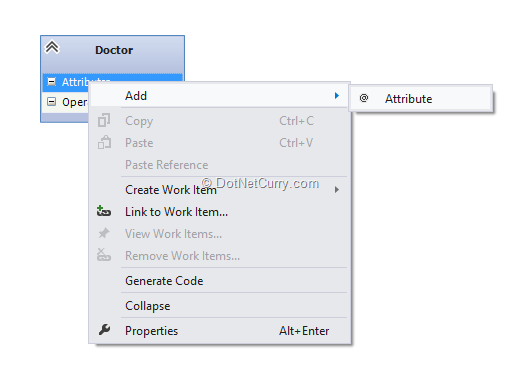
Step 3: Drag-Drop a class on the designer and rename the Class as 'Doctor'. This allows you to add Attributes (public properties) and 'Operations' (methods). Right click on athe ttribute and select Add Attribute as shown below:

Add the attribute as 'DoctorId' and set its properties as shown below:

Note here that the type can be set using the 'Type' property. The attribute can also be set with the unique property. So we can keep on adding attributes as per our requirements.
To add Operations (Method), right click on the operation and add the method. You can also set properties of the operation like input and output parameter and their type as shown below:

For specifying input parameter, click on the 'ellipsis' in front of the 'Parameters' property. You will see the following window:

Click on the 'Add' button. The parameter name and its type can be set:

Likewise, you can add various classes, interfaces and set the relation between them, for e.g. if the class needs to implement an interface, use 'Inheritance' symbol from the toolbox and drag-drop it from the class to the interface. The implementation relationship will look similar to the following:

Save the entire design.
The above steps are same in VS 2010 ultimate and VS 2012 Ultimate.
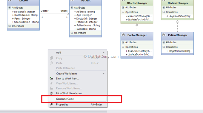
Step 4: Now to generate code, in VS2010 ultimate, VS Feature Pack 2 is required as mentioned at the beginning of this article. However in VS2012 ultimate, this feature is provided by default. Right click on the designer in VS 2012 and select 'Generate code' as shown below:

Here you will be asked about the 'Template binding' configuration as shown below:

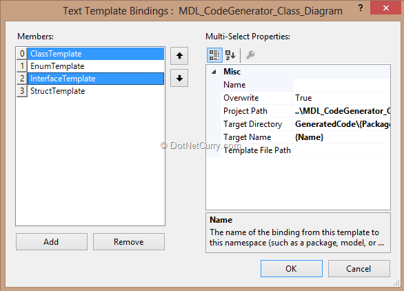
These are actually the 'Class Template', 'Interface Template' etc. So click on 'Yes' and you will see the template binding window:

Select 'ClassTemplate' and 'Interface' and click on 'OK'. You will see a new project has been added in the solution with source code files of all classes, interfaces to be used in the application, as shown below:

Conclusion
The UML Diagramming and code generation tool helps a Solution Architect setup boilerplate code for the rest of the team, thus reducing possible friction in design-intent and implementation.
This article has been editorially reviewed by Suprotim Agarwal.

C# and .NET have been around for a very long time, but their constant growth means there's always more to learn.
We at DotNetCurry are very excited to announce The Absolutely Awesome Book on C# and .NET. This is a 500 pages concise technical eBook available in PDF, ePub (iPad), and Mobi (Kindle).
Organized around concepts, this Book aims to provide a concise, yet solid foundation in C# and .NET, covering C# 6.0, C# 7.0 and .NET Core, with chapters on the latest .NET Core 3.0, .NET Standard and C# 8.0 (final release) too. Use these concepts to deepen your existing knowledge of C# and .NET, to have a solid grasp of the latest in C# and .NET OR to crack your next .NET Interview.
Click here to Explore the Table of Contents or Download Sample Chapters!

Mahesh Sabnis is a DotNetCurry author and a Microsoft MVP having over two decades of experience in IT education and development. He is a Microsoft Certified Trainer (MCT) since 2005 and has conducted various Corporate Training programs for .NET Technologies (all versions), and Front-end technologies like Angular and React. Follow him on twitter @maheshdotnet or connect with him on LinkedIn
Source: https://www.dotnetcurry.com/visualstudio/831/code-generation-uml-class-diagram-visual-studio-ultimate
Posted by: stroebeledienoes.blogspot.com
Posting Komentar untuk "Visual Studio 2015 Uml Class Diagram From Code"